
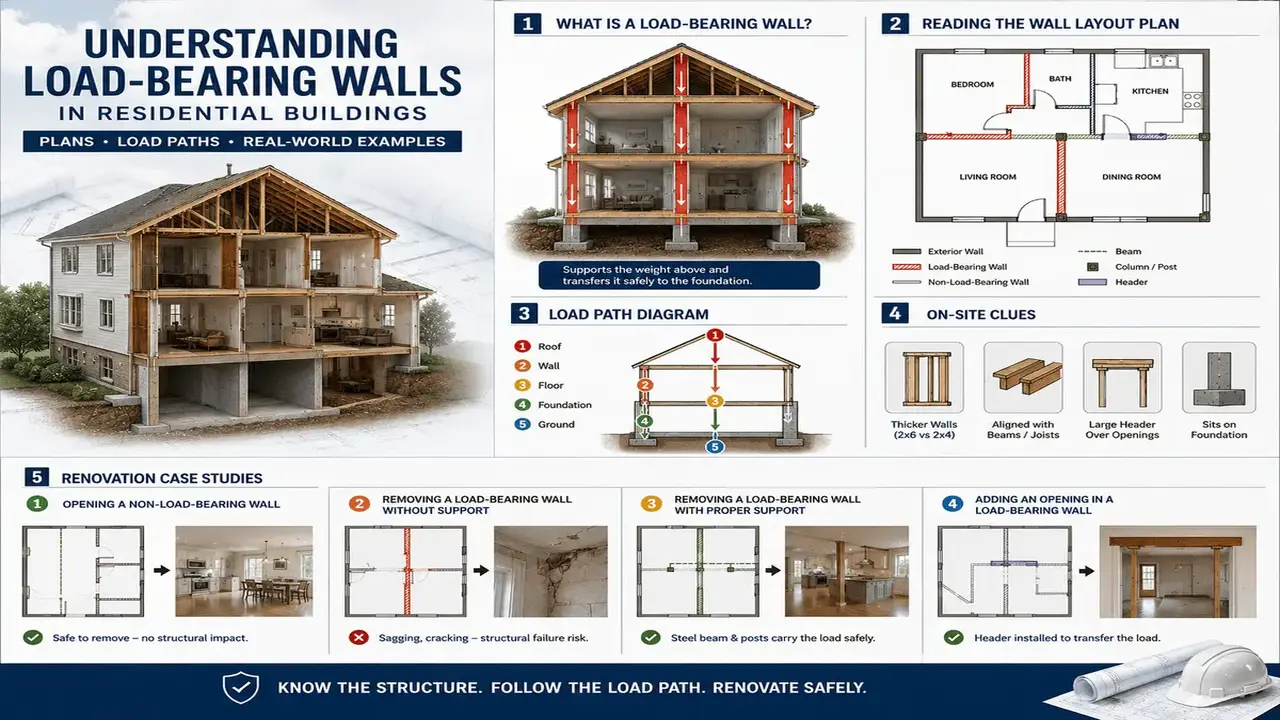
Understanding Load-Bearing Walls in Residential Buildings
Every home tells a story. The story of a cozy living room, a sun-drenched kitchen, or a master suite designed for relaxation. But beneath the paint, drywall, and floorboards lies an unspoken narrative—a silent, structural saga of forces, weights, and engineered compromises. This is the story of your home’s skeleton: the load-bearing wall.
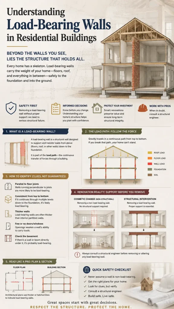
For the average homeowner, the thought of knocking down a wall to create an open-concept space is exhilarating. For a structural engineer, it’s a moment of deep calculation and caution. The difference between a successful renovation and a catastrophic collapse often comes down to one crucial question: Is that wall load-bearing?
This article is your definitive guide to understanding load-bearing walls in residential buildings. We will move beyond simple rule-of-thumb checklists and delve into the core principles of structural behavior. You will learn to read a wall layout plan like a professional, trace the invisible flow of gravity through a load path diagram, and examine real-world renovation examples that illustrate the difference between a cosmetic change and a structural intervention. By the end, you will possess the knowledge to ask informed questions, respect the integrity of your home, and avoid the most common and dangerous mistakes in residential renovation.
Part I: The Fundamentals – What Makes a Wall “Load-Bearing”?
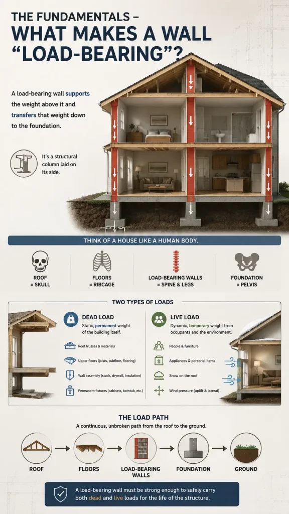
Before we can identify these critical elements, we must understand their function. A load-bearing wall is not simply a partition; it is a structural column laid on its side. Its primary job is to support the weight of the building above it and transfer that weight down to the foundation.
Think of a house like a human body. The roof is the skull, the floors are the ribcage, and the foundation is the pelvis. The load-bearing walls are the spine and legs. Without them, the structure collapses under its own weight.
This weight, or “load,” comes in two primary forms:
- Dead Load: The static, permanent weight of the building itself. This includes the roof trusses, roofing materials (shingles, tiles), the upper floors (joists, subfloor, flooring), the wall assembly itself (studs, drywall, insulation), and any permanent fixtures like cabinets or a bathtub.
- Live Load: The dynamic, temporary weight of the building’s occupants and their possessions. This includes people, furniture, appliances, snow on the roof, and even wind pressure (which can create both uplift and lateral loads).
A load-bearing wall must be robust enough to carry both of these loads safely for the entire lifespan of the structure. The key to doing this is creating a continuous, unbroken path from the roof to the ground. This is the “Load Path.”
How Does a Load Path Work?
Imagine a stack of blocks. If the top block is perfectly centered on the one below, the weight transfers directly down. If you offset it, the connection becomes unstable, and the stack is likely to topple. A load-bearing wall is the same.
Consider a typical two-story home with a basement.
- The Roof: The roof’s weight is concentrated on the ridge beam and the exterior walls. The roof rafters or trusses transfer this weight to the top plate of the exterior walls.
- The Second Floor: The second-floor joists span from one exterior wall to an interior support wall (or a central beam). The ends of these joists rest on the load-bearing wall’s top plate. This wall now carries the weight of the roof and the second floor.
- The First Floor: The load is transferred down through the wall’s studs to the bottom plate on the first floor. This bottom plate transfers the load to the first-floor subfloor, which then transfers it to the first-floor joists below.
- The Basement/Crawlspace: The first-floor joists transfer the combined load to a girder or a basement wall.
- The Foundation: The girder or basement wall transfers the entire load to the foundation walls or footings, which are wide concrete pads that spread the immense weight over a broad area of soil.
A non-load-bearing wall, or partition wall, does none of this. It only supports its own weight and the drywall nailed to it. It can be removed with minimal structural consequence, as long as the ceiling or floor above is self-supporting.
Part II: Reading the Blueprint – Demystifying Wall Layout Plans
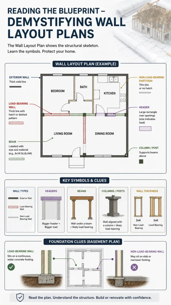
Identifying a load-bearing wall in the field starts with the single most important document: the Wall Layout Plan. This is not a simple floor plan showing room names. It is an engineered drawing detailing the structural skeleton. Learning to read these plans is your first line of defense against a dangerous assumption.
Key Symbols and Conventions
A construction drawing uses a specific visual language. Here are the critical elements to look for on a wall layout plan:
- Solid vs. Dashed Lines: This is the most fundamental distinction. Exterior walls are almost always drawn as thick, solid lines. Interior walls drawn with a single thick solid line are often load-bearing. However, many modern structural plans denote load-bearing interior walls with a specific hatch pattern (e.g., diagonal lines, a series of X’s) or a dashed line to distinguish them from non-structural partitions (often shown as thinner solid lines or no hatch).
- Dimensions and Callouts: Look for structural callouts. A wall might be labeled “10” CMU LOAD BEARING” (10-inch concrete masonry unit) or simply “L.B.” The thickness of the wall is a huge clue. A standard non-load-bearing interior wall is framed with 2×4 studs (3.5 inches thick). A load-bearing wall might be framed with 2×6 studs (5.5 inches thick) to allow for more insulation or to carry a higher load.
- Headers: Look for large rectangular symbols over door and window openings. These are headers—beams made of wood, steel, or engineered lumber (LVL/Microlam) that span the opening and transfer the load from above around the opening. The size and material of the header are directly proportional to the load it carries. A small, single 2×4 header is for a non-load-bearing closet. A massive, multi-ply 4×12 or a steel I-beam header is a dead giveaway for a load-bearing wall.
- Beams and Columns: The plan will show the location of critical support beams (often labeled with their size, e.g., “6×14 GLULAM” or “W8x18 STEEL”) and support columns or posts (often a dark square or circle). A wall that is located directly under a beam or aligns with a column is almost certainly load-bearing.
- Footings: The foundation plan is the final piece of the puzzle. A load-bearing interior wall in a basement will rest on a continuous concrete footing that is wider than the wall itself. A non-load-bearing basement wall might simply sit on a concrete slab. The plan will show the dimensions of these footings—the wider and deeper the footing, the heavier the load.
The “Stacking” Rule
The single most important rule for reading a wall layout plan is the Stacking Rule. A load-bearing wall must be continuous from the roof to the foundation. Therefore, look for walls that are stacked directly on top of each other from floor to floor.
- Examine the Roof Plan: Identify the walls directly under the ridge beam or under major roof truss points.
- Examine the Second Floor Plan: See if the second-floor joists run perpendicular to a wall or parallel to it. If the joists run perpendicular and land on top of a wall, that wall is almost certainly load-bearing. If the joists run parallel to the wall, the wall is likely a partition.
- Examine the First Floor Plan: Does a same wall exist directly below?
- Examine the Basement Plan: Is there a beam or a wall below it?
If you see a wall on the first floor that is directly under a wall on the second floor, and that second-floor wall is under the roof ridge, you have a triple-stacked load path. Never remove that wall without a plan.
Part III: Visualizing the Forces – Creating Your Own Load Path Diagram
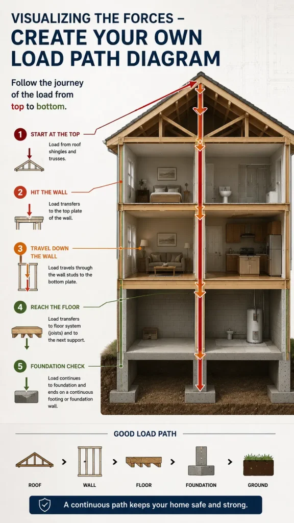
A wall layout plan is a static map. A Load Path Diagram is a dynamic story. It’s a simplified sketch that traces the journey of a single pound of force from the roof down to the ground. Creating one for your own home is the most powerful way to understand its structure.
How to Build a Load Path Diagram
You don’t need expensive software. A pen, paper, and your home’s floor plan are enough.
- Start at the Top: Pick a point on the roof, say, the ridge. Draw an arrow pointing straight down. This arrow represents the dead load of the roof shingles and trusses.
- Hit the Wall: The arrow travels down the roof truss to the exterior wall’s top plate. This is the first major transfer point.
- Travel Down the Wall: The arrow now goes down the center of the wall studs to the bottom plate. This represents the load traveling through the wall.
- Reach the Floor: The arrow hits the floor system. The floor joists are spanning between two supports. Is your arrow landing on a joist? If the wall is directly above a support (another wall or a beam), the arrow goes straight down. If the wall is in the middle of a joist span (cantilevered), the load path is more complex.
- Foundation Check: The arrow continues down to the basement or crawlspace. It must land on a concrete wall, a concrete column, or a steel post. If it lands on a simple wooden post sitting on a 4-inch concrete slab, you have a problem. A proper load path ends on a continuous footing or a robust foundation wall.
A Practical Example: The Girder and Post System
Imagine a house with a center hallway. On the first floor, this hallway is defined by two parallel walls. On the second floor, the hallway is gone, and the bedrooms span from one side of the house to the other.
- The Load Path:
- Roof: Weight goes to exterior walls.
- Second Floor: The joists span from exterior wall A to exterior wall B. They do not rest on any interior wall in the middle. Therefore, the second floor ceiling is not supported by the first-floor hallway walls.
- First Floor: The first-floor joists do span from the exterior walls to the center hallway walls. They land on the top plate of both hallway walls.
- Basement: Below the first floor, a large steel I-beam (girder) runs the length of the house, supported by steel columns every 10 feet. The first-floor hallway walls are directly above this beam. The beam’s load path goes to the steel columns, which go to concrete footings.
The Diagnosis: The first-floor hallway walls are load-bearing. They are carrying the entire first floor and everything on it down to the beam. The walls themselves are just the “packaging” for the structural support. The beam and columns are the true skeleton. You cannot remove these walls without first installing a new beam and columns—a major structural renovation.
Part IV: Lessons from the Field – Renovation Examples
Knowing the theory is one thing. Seeing it fail in the real world is the best teacher. Here are three renovation scenarios, ranging from simple to critical, that illustrate the concepts we’ve discussed.
Example 1: The “Easy” Kitchen Expansion – A Non-Load-Bearing Success
The Situation: Sarah and Tom wanted to open up their 1950s kitchen to the dining room. The wall between them was a standard 12-foot-long interior wall with a simple doorway.
The Investigation:
- Wall Layout Plan: The wall was parallel to the second-floor joists (visible through a ceiling access panel). This was the first huge clue.
- Load Path Diagram: The wall did not align with any beam or column in the basement. The basement had a central beam running perpendicular to this wall.
- Field Verification: The header over the doorway was a single 2×4 board. The wall studs were simply 2x4s with no unusual nailing patterns or doubled-up studs at the corners.
The Conclusion: The wall was a non-load-bearing partition. It was simply dividing the space.
The Renovation: The wall was safely removed without any structural reinforcement. No beam was needed. The ceiling was patched, and new flooring tied the two rooms together. The project was completed by a general contractor with no engineering involvement. The cost was minimal, and the result was a beautiful, open-concept space.
Lesson: When a wall runs parallel to the floor joists above and does not support a floor or roof above, it is almost certainly non-load-bearing. Always verify the joist direction.
Example 2: The “Open Concept” Master Bedroom – A Beam is Required
The Situation: Mark and Jen wanted to create a large master suite by combining two smaller bedrooms and a hallway. The wall they wanted to remove was a 15-foot section between the old master and the hallway.
The Investigation:
- Wall Layout Plan: This wall was perpendicular to the second-floor joists. The floor plan showed that the second-floor joists were designed to land on this wall.
- Load Path Diagram: This wall was stacked directly above a basement wall. In the basement, directly below this wall, was a 2×6 framed wall that rested on a concrete footing.
- Field Verification: The header over a small closet door in this wall was a massive 4×12 beam. The wall was constructed with 2×6 studs. This was a clear sign of high load.
The Conclusion: This was a load-bearing wall. It was supporting the second-floor joists and transferring all that load down to the foundation.
The Renovation: They could not simply remove the wall. The solution required a structural engineer’s design: a 16-foot, 8-inch deep LVL (Laminated Veneer Lumber) beam would need to be installed to span the opening. The ends of this new beam would need to be supported by load-bearing columns (typically 2×4 or 4×4 wood studs, or steel posts) that were framed down into the basement, transferring the load to the basement wall. This required temporary shoring, cutting into the floor joists, and achieving specific connections. The cost was several thousand dollars for engineering and materials.
Lesson: A wall perpendicular to the floor joists above, and stacked on a foundation element below, is load-bearing. Creating an opening requires a properly engineered beam and support columns. This is not a weekend DIY project.
Example 3: The “Disaster” – A Cautionary Tale
The Situation: An investor bought a 1970s split-level home. The main floor had a huge, wide opening between the living and dining areas. The investor decided to remove the 8-foot section of wall on one side of the opening to make the space even larger. He did not consult an engineer.
The Investigation (After the Collapse): The wall he removed was directly under the main roof ridge. The second floor hallway above had a massive dip and sag. The ceiling below the removed wall was cracking. The next floor above had a large crack in the drywall.
- Load Path Diagram (Post-Mortem): The ridge beam of the roof was supported at one end by an exterior wall. Its other support was this very 8-foot wall section that the investor removed. By removing it, he effectively removed the only support for that end of the roof ridge. The ridge beam now had a span of 30 feet unsupported. The load of the entire roof was now hanging from the second-floor ceiling joists, which were never designed to carry that load.
The Consequence: The second-floor joists began to deflect (bend) severely. This caused the floor above to sag, the ceiling below to crack, and the wall to become structurally unstable. The entire corner of the house was compromised. The repair required a structural engineer to design a temporary shoring plan, a new steel beam and posts, and a complex renovation to reinforce the failing floor system. The total repair cost exceeded $40,000, not including the loss of value and the legal liability.
Lesson: Never, ever assume. A wall that looks small or insignificant can be holding up a major structural element like a roof ridge. The “Stacking Rule” is not a suggestion; it is a law of physics. When in doubt, pay for a structural engineer. The $500 consultation fee is cheap compared to a $40,000 repair and the risk of injury or death.
Conclusion: Respect the Skeleton
Understanding load-bearing walls is not about memorizing a checklist of “clues.” It is about developing a structural mindset. It is about looking at your home not as a collection of rooms, but as a system of forces.
Every time you stand in a room, you are standing on a system of joists, beams, columns, and walls that are holding you up. Every nail, every stud, every header was placed with a purpose. When you renovate, you are altering that system.
Before you pick up a sledgehammer, follow this protocol:
- Get the Blueprints: Contact your local building department or the original architect. A set of structural drawings is the most valuable tool you can have.
- Learn to Read Them: Understand the symbols. Identify the solid lines, the hatch patterns, and the beam callouts.
- Create a Load Path Diagram: Trace a single pound of weight from your roof to your basement. This will expose the true spine of your home.
- Hire a Professional: If you have any doubt about a wall, if it is perpendicular to the joists, if it runs under a ridge beam, or if it aligns with a foundation element, call a structural engineer. They are the doctors for your home’s skeleton. They can provide a stamped plan for a beam, a column, or a temporary shoring system that will keep your family safe and your home sound.
The most beautiful renovation is one that is both aesthetically pleasing and structurally sound. By understanding the hidden skeleton of your home, you can create a space that is not only a joy to live in but also a monument to intelligent, responsible construction. Do not outsmart your home’s structure. Respect it.
Check: Mastering the Blueprint: The Ultimate Guide to Small Living Room Furniture Layouts
Check: Reinforced Concrete High-Rise Buildings: Key Construction Components Explained
Check: The Institution of Civil Engineers homepage | Institution of Civil Engineers (ICE)