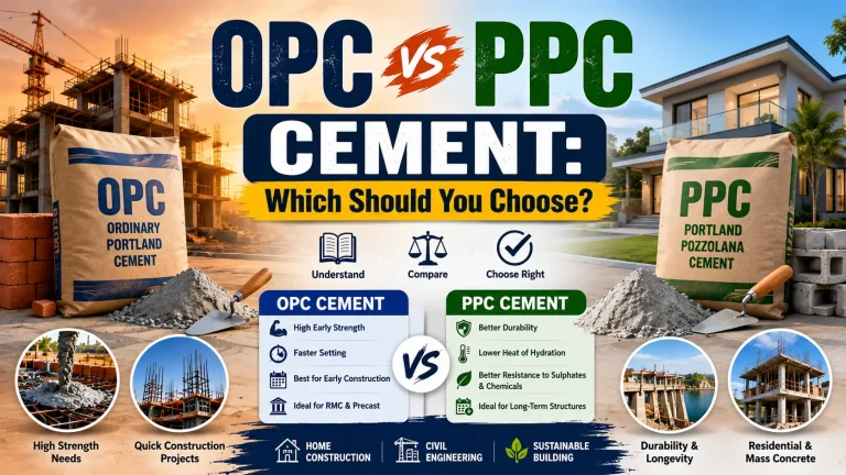

Reinforced Concrete High-Rise Buildings: Key Construction Components Explained
A Complete Guide to How Modern Skyscrapers Stand Tall and Safe
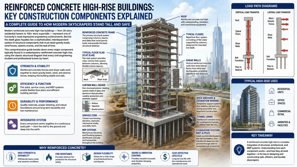
Modern reinforced concrete high-rise buildings — from 20-story residential towers to 100+ story supertalls — represent one of humanity’s most impressive engineering achievements. Behind the sleek glass façades lies a sophisticated, interdependent system of structural components that must resist gravity loads, wind forces, seismic events, and the test of time.
This comprehensive guide breaks down every major component typically found in a contemporary reinforced concrete high-rise, using the classic structural diagram that every civil engineering student and professional knows by heart.
Check: Designing with Cold in Mind -Sustainable Architecture · Sweden Guide
Check: Flat Slab vs Beam Slab – Detailed Comparison
1. Foundations: Where Everything Begins
No high-rise can exist without transferring millions of tons of load safely into the ground.
a) Raft (Mat) Foundation
A thick reinforced concrete slab (usually 2.5–5 m / 8–16 ft) that spreads the building’s load over a large area. Common in medium-rise (20–40 stories) on moderate soils.
b) Deep Piled Foundations
Driven or bored piles (often 40–100 m deep) transfer loads to stronger soil layers or bedrock. In supertalls, barrette piles or large-diameter caissons are used.
c) Combined Pile-Raft System (Most Common 2025–2026)
Piles handle concentrated column loads while the raft resists bending and distributes uniform live loads. This hybrid approach reduces differential settlement and is the global standard for buildings over 150 m.
Real-world example: The 432 Park Avenue tower in New York (425 m) uses a 3 m-thick mat supported by high-capacity rock anchors and caissons socketed into Manhattan schist.
2. The Structural Core: The Building’s Spine
The central core is the single most important lateral and vertical load-resisting element.
a) Reinforced Concrete Shear Walls
Typically 300–800 mm thick, these walls surround elevators, stairs, and risers. They provide the majority of lateral stiffness against wind and earthquakes. Outrigger and belt truss systems connect the core to perimeter columns in supertalls, reducing drift and increasing efficiency.
b) Service Core Layout
Contains:
- High-speed elevators (passenger & service)
- Emergency stairwells (pressurized for fire safety)
- MEP risers (chilled water, electrical busducts, telecom)
- Refuge floors (every 15–20 stories in many jurisdictions)
3. Floor Systems: Three Main Options in 2025–2026
The choice dramatically affects speed, cost, and architectural flexibility.
a) Flat Plate / Flat Slab (Most Popular for Residential & Hotels)
Concrete slab (200–350 mm thick) poured directly onto columns without beams. Advantages:
- Lower floor-to-floor height (saves 300–500 mm per floor)
- Completely open floorplates
- Faster construction (no beam formwork)
Used in 70% of new concrete residential high-rises worldwide.
b) Beam-and-Slab System
Traditional beams transfer slab loads to columns. Still common in office buildings needing heavier live loads.
c) Post-Tensioned (PT) Slabs
High-strength cables are tensioned after concrete hardens, allowing longer spans and thinner slabs (as low as 180 mm for 9–10 m spans). Dominant in Middle East and Australian high-rises.
4. Columns and Vertical Elements
- Size typically reduces with height (e.g., 1.2 × 1.2 m at base → 600 × 600 mm at top)
- High-strength concrete (C60/75 to C100/115) used in lower 20–30 floors
- Often contain embedded steel sections (SRC — steel-reinforced concrete) in seismic zones
5. Curtain Wall Façade System: The Building’s Skin
Modern high-rises are not “concrete buildings with windows” — they are concrete structures wrapped in lightweight cladding.
Components:
- Vision glass & spandrel panels
- Aluminum mullions and transoms
- Unitized panels (factory-assembled, crane-installed — fastest method)
- Pressure-equalized rain-screen design prevents water infiltration
Weight: Only 50–80 kg/m² vs. 300–500 kg/m² for traditional masonry — crucial for reducing foundation loads.
6. MEP Integration: The Hidden Lifelines
Mechanical, Electrical, and Plumbing systems account for 25–35% of total construction cost.
Vertical distribution:
- Chilled water risers in core
- Electrical busducts (up to 5000 A)
- Fire sprinkler mains
- Telecom and data risers
Horizontal distribution:
- Underfloor ducts or raised access flooring (office buildings)
- Ceiling zones with multi-trade rack systems
7. Lateral Load Resisting Systems: Fighting Wind and Earthquakes
Three primary strategies (often combined):
- Core-only system (up to ~50 stories)
- Core + outrigger/belt truss (50–100+ stories) — connects core to perimeter columns at 2–3 mechanical floors
- Tube-in-tube or bundled tube (legacy of Fazlur Khan’s innovations)
Example: The 599 m Ping An Finance Center in Shenzhen uses four levels of outriggers, reducing steel usage by 20%.
8. Construction Sequence: From Excavation to Topping Out
- Site excavation & temporary retention (diaphragm walls, secant piles, rock anchors)
- Bottom-up foundation construction
- Core construction using jump forms or slip forms (core rises 3–7 days per floor)
- Floor slabs follow 3–10 floors behind using table forms or aluminum formwork
- Curtain wall installation starts ~15 floors below slab construction
- MEP rough-in and interior fit-out proceed floor-by-floor
Fastest 2025–2026 speeds: 3–4 days per floor (Broad Group’s “BCORE” system claims 1 floor/day with prefabricated elements).
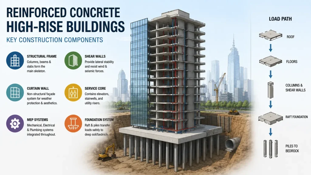
9. Load Paths Demystified
Understanding how forces travel through the building is fundamental.
Gravity Load Path:
Roof → Slab → Beams or directly to columns → Transfer girders (if needed) → Columns → Raft/Piles → Ground
Lateral Load Path (Wind/Earthquake):
Façade → Floor diaphragms (act as rigid plates) → Shear walls/core → Foundations → Soil/Rock
10. Sustainability Features in Modern Concrete High-Rises (2025–2026)
- 40–60% GGBS or fly-ash replacement reduces embodied carbon
- Thermal mass of concrete used for passive cooling
- Double-skin or triple-glazed curtain walls
- Embodied carbon now reported on every major project (target <500 kg CO₂e/m²)
Summary Diagram: Key Components at a Glance
| Component | Primary Function | Typical Material/Detail |
|---|---|---|
| Piles + Raft | Transfer loads to ground | High-strength concrete C60–C100 |
| Shear Walls/Core | Resist lateral forces | 400–800 mm thick, heavily reinforced |
| Flat Slab / PT Slab | Floor structure | 200–350 mm thick |
| Columns | Vertical load transfer | Reducing size with height |
| Outriggers (supertalls) | Engage perimeter columns | Steel or concrete at mechanical floors |
| Curtain Wall | Weather envelope & aesthetics | Unitized glass/aluminum |
| MEP Risers | Building services | Centralized in core |
Why Reinforced Concrete Remains King for High-Rises
- Superior fire resistance (2–4 hours inherent)
- Excellent acoustic separation
- High thermal mass
- Local materials and labor
- Proven durability (many 100-year-old concrete buildings still in service)
While structural steel dominates in the United States and parts of Asia for the very tallest icons, reinforced concrete — often in composite systems — remains the most common structural material worldwide for buildings between 20 and 150+ stories.
The next time you look up at a modern high-rise, you’re not just seeing glass and concrete — you’re seeing a carefully orchestrated symphony of engineering components working together in perfect harmony.
check: The Institution of Civil Engineers homepage | Institution of Civil Engineers (ICE)