Space Planning for a House: A Technical and Practical Approach
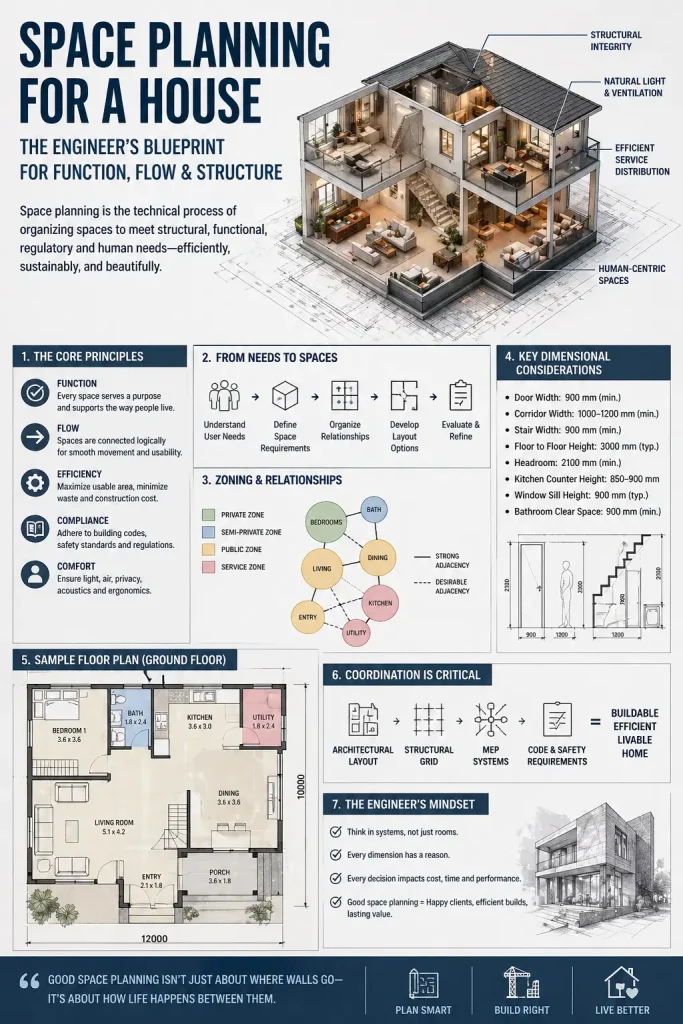
Space planning for a house is far more than an exercise in aesthetic arrangement or furniture placement. For the engineer or constructor, it is a fundamental, technical process—a systems integration challenge that sits at the very core of building design. It is the disciplined art and science of organizing three-dimensional volumes and their two-dimensional projections to satisfy a complex, often conflicting, matrix of requirements: structural logic, building physics, service distribution, human behavior, regulatory codes, and economic efficiency. This article deconstructs that process, moving beyond conceptual diagrams to the hard logic, dimensional constraints, and coordination protocols that transform a client’s wish list into a buildable, efficient, and livable home.
1. Defining the Technical Process: Beyond “Arranging Rooms”
At its essence, residential space planning is the optimization of enclosed volumes within a structural and regulatory envelope to maximize functional utility, constructability, and occupant well-being. It is a precursor to, and a driver of, all subsequent design and engineering decisions. A poor spatial layout cannot be fully corrected by superior finishes or advanced systems; its flaws are embedded in the building’s DNA, leading to wasted materials, inefficient services, poor environmental performance, and compromised livability.
The engineer’s mindset shifts the focus from “what looks good” to “what works efficiently and can be built soundly.” This involves:
- Quantifiable Metrics: Measuring efficiency (net-to-gross ratios, circulation percentages), ergonomics (clearance zones, work triangles), and environmental performance (daylight factors, thermal zoning).
- Constraint Mapping: Understanding the non-negotiable boundaries: structural grid spacing, maximum cantilever lengths, minimum code-mandated dimensions, and service shaft locations.
- Sequential Integration: Recognizing that space planning is not a linear step but an iterative loop with structural design, MEP (Mechanical, Electrical, Plumbing) engineering, and code compliance. A change in one domain reverberates through all others.
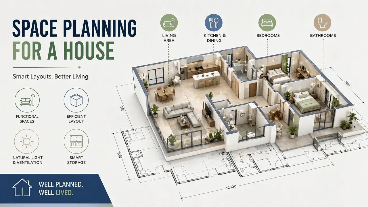
2. Functional Zoning: The First Layer of Organization
The initial and most critical segmentation of the plan is into functional zones. This is not about architectural style but about logical grouping based on activity, noise level, privacy requirement, and service dependency. Proper zoning is the primary tool for minimizing disruptive circulation and optimizing environmental control.
a. Public Zone (Social/Formal)
- Components: Formal living room, dining room, entry foyer, guest toilet (powder room), sometimes a home office if client-facing.
- Location Logic: Positioned for immediate access from the main entrance. This creates a clear “public face” of the home, allowing guests to be received without penetrating private areas.
- Engineering Implications:
- Acoustics: Requires deliberate separation from private and service zones. This may influence wall construction (double stud, increased mass) and placement of buffer spaces (stair halls, storage).
- Circulation: Should have a dedicated, direct path from entry to main living spaces, often via a foyer that acts as an acoustic and visual buffer.
- Services: May require less intensive plumbing (only a guest toilet) but more robust electrical circuits for lighting and entertainment systems. Often benefits from the best orientation and views.
b. Private Zone (Rest/Personal)
- Components: Bedrooms (master and secondary), family bathrooms, private studies, dressing rooms.
- Location Logic: Positioned away from the main entrance and public zones, typically towards the rear or quieter sides of the plot. Should be accessed via a dedicated “private corridor” to avoid passing through public spaces.
- Engineering Implications:
- Privacy: Requires visual separation (window placement, fencing) and acoustic insulation from both public and service zones.
- Thermal Zoning: Bedrooms often have different heating/cooling preferences (cooler for sleeping). Grouping them allows for efficient zone control in HVAC design.
- Daylighting: Bedrooms benefit from morning sun (East orientation) but require careful window placement to avoid overlooking neighbors for privacy.
c. Service Zone (Support/Utility)
- Components: Kitchen, utility room, laundry, mudroom, pantry, garage access, mechanical/boiler room, bulk storage.
- Location Logic: Should be clustered and connected to secondary access points (back door, garage, service lane). Proximity to the kitchen is key for the “dirty” flow of groceries, waste, and laundry.
- Engineering Implications:
- Plumbing Stack Efficiency: This is the primary driver for service zone placement. All wet rooms (kitchen, bathrooms, laundry) should be stacked vertically to minimize horizontal pipe runs and simplify the plumbing core. A compact, vertical “service spine” is the gold standard.
- Ventilation: Requires direct exhaust paths to the outside (kitchen hood, dryer vent, bathroom fans). This influences wall placement and roof detailing.
- Noise & Odor: Must be acoustically and olfactorily buffered from living and sleeping areas. Locating them on the “cold” facade (North/West in cold climates) can help contain heat loss.
Technical Note on Zoning Efficiency: Each zone should have a clear “address” on the plan. Overlapping zones (e.g., a bedroom opening directly into the living room) create functional conflict and inefficient circulation. The ideal layout has a central circulation core (hall, stairs) from which spokes lead to distinct zone clusters. This minimizes cross-traffic.
3. Space Standards & Dimensional Logic
While local building codes establish minimums for safety (egress, fire separation), functional dimensions are derived from ergonomic studies, furniture standards, and human movement patterns. These are the “rules of thumb” that prevent a space from feeling cramped or being unusable.
- Room Areas: The listed minima (Living: 12-20m², Master Bed: 12-16m²) are for basic comfort with standard furniture. A modern open-plan living/kitchen/dining area for a family often exceeds 30m². These are starting points for client discussion.
- Circulation Widths:
- Corridors/Hallways: 900mm is the absolute minimum for single-file passage (often cited in codes for escape routes). For daily living, 1000-1200mm is the practical minimum. A 1200mm hall allows two people to pass comfortably or one person with a stroller/trolley.
- Doorways: 800mm is standard for internal doors. Main entry doors should be 900-1000mm to accommodate moving furniture and accessibility. Door swings must be considered in the plan—a door opening into a corridor can effectively reduce its width.
- Stair Dimensions (Critical for Safety & Comfort):
- Riser (R): 150-175mm. Lower is easier to ascend, but increases tread run and stair length.
- Tread (T): 250-300mm (excluding nosing). Must provide adequate foot space.
- Width: 900mm minimum clear width (handrails can encroach slightly). For primary stairs in a home, 1000-1200mm is far more comfortable.
- The Golden Formula:
2R + T = 600-630mm. This ergonomic relationship ensures a natural, safe stride. Deviating from this (e.g., high risers with shallow treads) creates a tiring, hazardous stair.
Regional Code Integration: While Eurocodes provide structural standards, dimensional requirements come from national annexes or local regulations (e.g., Germany’s Bauordnung, Sweden’s BBR – Boverkets byggregler). The planner must know these: minimum room heights (often 2.4m), window sizes for light and ventilation, and specific accessibility requirements (e.g., for elderly-friendly housing).
4. Circulation Planning: The Arteries of the Home
Circulation is the movement infrastructure. It is dead space—area that generates no direct utility but is essential for access. The goal is to make it as efficient, safe, and unobtrusive as possible.
a. Horizontal Circulation
This includes hallways, lobbies, and the clear floor space required in front of doors and around furniture.
- Efficiency Metric: Circulation area (halls, stairs, landings) should not exceed 10-15% of the total net floor area. A plan exceeding 20% is highly inefficient, indicating poor zoning or over-fragmented spaces.
- Design Principles:
- Minimize Length: Use a central spine (main hall) with direct spokes to rooms. Avoid “maze-like” layouts.
- Avoid Cross-Flow: Public circulation should not cut through private zones or service areas. A person going from the kitchen to the garage should not walk through the living room or past bedroom doors.
- Landing Efficiency: Stair landings should be functional—large enough for a person to pause, turn, or place items, but not wasteful. A landing at the top of stairs can serve as a small balcony or reading nook.
b. Vertical Circulation
Stairs are the most space-intensive and technically demanding circulation element.
- Spatial Impact: A straight flight of stairs with 14 risers (typical for a 2.7m floor-to-floor height) requires a run of ~3.5m (14 x 0.25m tread). This is a significant linear footprint.
- Design Variations & Trade-offs:
- Straight Run: Most efficient in terms of tread/riser ergonomics and construction simplicity. Requires the longest uninterrupted run.
- L-Shaped (with landing): Saves space by turning 90°. Landing size adds to footprint but can be a design feature.
- U-Shaped/Winder: Most space-saving but complex to design ergonomically (treads narrow on the inside). Requires careful calculation to meet the
2R+Tformula on all steps.
- Headroom: A critical and often overlooked constraint. The minimum headroom on stairs is typically 2.0m (code), but 2.1m+ is desirable. This affects the design of upper-floor landings and the relationship between stair run and floor levels above.
5. Adjacency Planning: The Logic of Connection
This is the relationship diagramming that precedes bubble diagrams. It defines which spaces need to be near each other and how (direct connection, visual link, acoustic separation). This is a matrix of priorities.
Critical Adjacencies (High Priority – “Must-Have”):
- Kitchen ↔ Dining: Direct, open connection is essential for serving and social interaction. A door is often a barrier.
- Kitchen ↔ Pantry/Utility: Close, preferably with a “dirty” circulation path to the back door/garage.
- Master Bedroom ↔ En-Suite Bathroom & Dressing: Integrated, private cluster.
- Bedroom ↔ Bathroom (Shared): Proximity is key, but not at the expense of bedroom privacy (avoid bathroom door opening directly onto bed).
- Living Room ↔ Outdoor Space (Patio/Garden): Visual and physical connection (large doors, aligned thresholds) expands living area.
Desirable Adjacencies (Medium Priority):
- Home Office ↔ Quiet Zone: Away from main living noise but accessible.
- Guest Bedroom ↔ Guest Bathroom: Convenient for visitors without invading family privacy.
- Laundry ↔ Bedrooms: For ease of putting away clothes, but consider noise (laundry machines) and potential water leak risks.
Negative Adjacencies (To Be Avoided):
- Living Room ↔ Noisy Service Area (Laundry/Boiler Room): Acoustic isolation required.
- Bedroom ↔ Main Entrance/Foyer: Noise and light disturbance.
- Kitchen ↔ Formal Dining (if separate): Creates a “back-of-house” vs “front-of-house” divide that hinders informal family dining.
Tool: An Adjacency Matrix is invaluable. Rows and columns list all rooms. Cells are marked: ++ (essential connection), + (desirable), 0 (neutral), - (avoid). This quantifies relationships and guides bubble diagramming.
6. Structural Integration: The Unmovable Grid
Space planning must occur within, and in respect to, the primary structural system. Ignoring this leads to impossible designs, costly structural modifications, and compromised ceiling heights.
Primary Structural Systems & Their Spatial Implications:
- Load-Bearing Walls (Masonry/Timber Frame):
- Constraint: Walls are fixed, massive, and difficult to relocate.
- Planning Implication: The layout must be designed around the structural wall grid, especially on lower floors where they may support upper floors. Open-plan areas are created by identifying which walls are not structural. This requires early structural engineer input.
- Avoid: Creating large rooms that require the removal of a suspected load-bearing wall without verification.
- Reinforced Concrete (RC) Frame:
- Constraint: The column grid dictates the fundamental spatial rhythm. Typical residential grids are 3m, 4.5m, 6m, or multiples thereof.
- Planning Implication: Room dimensions and partition walls should align with the grid. A wall placed midway between columns may be fine, but a wall that ends at a column is structurally sound and easier to detail. Long spans (>6m) require deeper beams, reducing headroom.
- Key Integration Point: Beam depth. A beam spanning 6m might be 400-600mm deep. This “lost” vertical space must be accounted for in room height planning, especially in basements or under sloping roofs.
- Timber Floor Joists (I-Joists/Solid):
- Constraint: Joists run in one direction (typically the shorter span). Openings (stairwells, large doorways) require header beams (LVL, steel flitch) that concentrate load.
- Planning Implication: Major penetrations and point loads (e.g., a heavy bathtub) must be coordinated with the joist layout. Plumbing stacks should ideally run parallel to joists to minimize notching (which weakens them) or require costly boxing.
The Cardinal Sin: Designing a beautiful, free-form layout on paper, only to discover that a major wall crosses a main beam or column, requiring a complex and expensive structural transfer. The rule is: structural grid first, then infill walls.
7. Building Services Coordination: The Hidden Network
Services are the building’s nervous, circulatory, and respiratory systems. Their routing dictates wall placements, ceiling heights, and floor build-ups. Early, rough coordination is non-negotiable.
a. Plumbing & Drainage (The Gravity-Driven Spine)
- The Golden Rule: “Stack and Drop.” All fixtures (toilets, showers, sinks, washing machines) must drain by gravity to the main soil stack. This stack must be as vertical and centralized as possible.
- Planning Action:
- Identify all wet rooms (kitchen, all bathrooms, laundry).
- Group them around a central plumbing core (a shaft that runs from roof to foundation).
- Ensure this core can be aligned vertically across floors. A bathroom on Floor 2 must be directly above or below one on Floor 1.
- Minimize horizontal drain runs (max slope 1-2%). Long horizontal runs require deeper floor build-ups or larger pipes, increasing cost.
- Consequence of Failure: A poorly placed bathroom forces pipes to run long distances under floors or through multiple rooms, increasing cost, risk of leaks, and reducing ceiling height.
b. Electrical & Data (The Network)
- Planning Action:
- Panel Location: The main distribution board (fuse box) should be central and accessible. This influences cable run lengths.
- Circuit Logic: Group outlets and lights by room and function (e.g., kitchen countertop circuits, living room lighting circuit). This dictates wiring routes.
- Special Circuits: Identify high-load areas early (kitchen, EV charger, workshop) for dedicated circuits and appropriate wire gauges.
- Data/AV: Plan for coaxial and ethernet runs to living areas, home office, and potential future TV locations. Consider conduit for future upgrades.
- Coordination Tip: Avoid running electrical conduits in the same stud cavity as plumbing supply lines (risk of condensation, corrosion). Maintain separation per code.
c. HVAC & Ventilation (The Climate Control)
- Heating/Cooling Distribution:
- Hydronic (Radiators/UFH): Requires space for pipes and manifolds. Underfloor heating (UFH) demands a raised floor build-up (50-100mm), impacting door clearances and transitions.
- Ducted Air (VRV/VRF or Central AC): Requires duct shafts and ceiling space. Supply and return air paths must be planned. Ducts are bulky (200x200mm min) and constrain structural and ceiling design.
- Ventilation:
- Natural Cross-Ventilation: Requires windows on opposite walls. This influences room shape and external wall placement.
- Mechanical Ventilation (MVHR): Requires a central unit and ducted supply/return to all habitable rooms. This creates a service zone in the ceiling or a dedicated cupboard, impacting room layouts above.
- The “No-Fly Zone”: Avoid placing ducts, large pipes, or structural beams in the middle of a room’s ceiling. They should be routed along perimeter walls or in designated service zones (hallways, utility rooms).
The Coordination Meeting: The most effective tool is a “clash detection” session with the architect, structural engineer, and MEP engineers using a shared BIM model or layered drawings. The question is always: “Can this pipe/duct/beam run through this space without conflicting with another system or reducing headroom below code?”
8. Environmental & Contextual Integration
Space planning is not done in a vacuum. It must respond to the site’s climate, orientation, and surroundings to achieve passive performance.
a. Orientation & Solar Gain (Cold Climates Focus)
- Primary Living Spaces (Living, Kitchen, Dining): Maximize South-facing glazing for passive solar heat gain in winter. Use overhangs or shading devices to prevent summer overheating.
- Bedrooms: East-facing for gentle morning sun. Avoid West-facing for primary bedrooms in hot climates (afternoon heat gain).
- Service Areas & Garages: Position on North or West facades. They act as buffer zones, shielding living spaces from cold north winds or hot afternoon sun. Their lower thermal requirement makes them ideal for this location.
- Technical Note: Calculate the Window-to-Floor Area Ratio (WFR). A common guideline is 10-20% for adequate daylight without excessive heat loss/gain. Deep-plan rooms (center > 6m from a window) will be dark and require artificial lighting.
b. Daylighting Strategy
- Rule of Thumb: A room should have daylight on at least two walls if possible, or a very large window on one wall. Corner locations are ideal.
- Avoid Deep Cores: A central room with no external walls (e.g., a bathroom in the middle of a house) requires either a light well (expensive) or mechanical ventilation and artificial lighting. This is a planning failure.
- Reflective Surfaces: Light-colored interior walls and ceilings bounce daylight deeper into a space.
c. Thermal Zoning
Group spaces with similar heating/cooling schedules and setpoints.
- Day Zone: Living, kitchen, dining (heated/cooled during day/evening).
- Night Zone: Bedrooms (heated/cooled primarily at night).
- Buffer/Transition Zones: Halls, stairs, utility rooms, garages. These can have lower temperature setpoints or be unconditioned, reducing energy load. Placing them on the “cold” side of the house protects the conditioned core.
9. Ergonomics & Human Factors: The Scale of the Body
A dimensionally correct room can be a nightmare to use if furniture and movement are not considered from the start.
- The Kitchen Work Triangle: The path between Sink, Cooktop (Stove), and Refrigerator. Each leg should be 1.2m – 2.7m. Total triangle perimeter 3.6m – 8.5m. No major traffic should cross this triangle. This dictates the layout (U-shaped, L-shaped, galley).
- Furniture Clearances:
- Bed: Minimum 600mm clearance on sides for making the bed. 900mm+ on the side used for access.
- Dining: 900mm clearance behind chairs for pulling out. 600mm between table and wall for circulation.
- Seating Areas: 500-700mm between sofa and coffee table. 800mm+ for main walkways behind seating.
- Appliance Clearances: Refrigerator door swing (typically 900mm+), dishwasher opening, oven door pull-down (requires 900mm+ clear space in front).
- Turning Radius: For accessibility, a wheelchair requires a 1500mm diameter turning circle. This impacts hallway widths, room entry points, and bathroom layouts. Even for non-accessible design, a 1200mm clear circle is good practice for ease of movement.
The “Furniture Plan” is not an afterthought. It is a mandatory overlay on the space plan. Draw all major furniture to scale (beds, sofas, tables, appliances) before finalizing wall positions. This reveals conflicts like a door opening into a bed or a TV being too far from a sofa.
10. Flexibility & Future Adaptability
A home must serve its occupants for decades. Space planning should anticipate change.
- Structural Grid for Adaptability: A regular column grid (e.g., 3m or 4.5m) allows future non-load-bearing partitions to be relocated. Avoid placing all structural elements in a way that locks in room shapes.
- Multi-Functional Spaces: A guest bedroom can be a home office with a fold-down bed. A formal dining room can be a playroom. Design with flexible storage and minimal fixed elements.
- “Rough-In” for Future Services: Run empty conduit or spare capacity in service shafts for future technology (smart home wiring, additional data points, future solar/battery connections). Oversize main electrical panels slightly.
- Lifecycle Considerations: Place at least one bedroom and bathroom on the ground floor for potential aging-in-place. Design doorways and hallways to a width (900mm+) that could accommodate a wheelchair with minor modification.
11. Quantitative Efficiency Metrics
The engineer measures success in numbers.
- Net-to-Gross Floor Area Ratio (Efficiency Ratio):
- Net Internal Area (NIA): Usable, conditioned space within finished walls.
- Gross Floor Area (GFA): Total footprint including walls, circulation, and service shafts.
- Target: 75-85% is considered good for residential. A ratio of 70% indicates excessive circulation or thick walls. >90% is often unrealistic due to necessary structural elements.
- Calculation:
(NIA / GFA) x 100%. This is a key metric for client value—they pay for GFA but live in NIA.
- Circulation Area Percentage: As stated, target ≤15%. This includes halls, stairs, landings, and the space lost to door swings.
- Compactness Ratio (Surface Area to Volume): A more compact shape (closer to a cube) has less surface area relative to its volume, reducing heat loss/gain. Complex, sprawling plans with many nooks are thermally inefficient. This influences the overall massing before room-by-room planning.
12. Compliance & Regulatory Maze
Space planning must navigate a dense web of regulations. Failure here invalidates the design.
- Fire Safety (Most Critical):
- Escape Routes: Every bedroom must have a safe, unobstructed path to the outside. Typically, this means a door to a hallway that leads directly to an exit. Hallways must be a minimum width (often 900mm).
- Travel Distance: Maximum distance from any point in a home to an exit is limited (e.g., 30m in many codes). This can dictate the need for a second stair or exit in larger homes.
- Door Swing: Egress doors (bedrooms, main exit) must swing in the direction of exit travel in many cases.
- Fire Separation: Garages must be fire-separated from the main house (specific wall/floor construction, self-closing door).
- Accessibility (Universal Design):
- While full wheelchair accessibility is not always mandatory in single-family homes, visitability standards are increasingly adopted. Key requirements: at least one zero-step entrance, doors ≥ 800mm clear width, a bathroom on the ground floor that can be adapted.
- Turning Radius: The 1500mm circle mentioned earlier.
- Local Building Regulations (e.g., Swedish BBR): These are exhaustive. They cover:
- Room Heights: Minimum 2.4m in habitable rooms.
- Window Sizes: For light and ventilation (e.g., window area ≥ 1/10th of room floor area for light, 1/20th for ventilation).
- Sound Insulation: Minimum requirements for airborne and impact sound between dwellings and between rooms (e.g., Rw 55 dB for walls).
- Energy Performance: U-value requirements for walls, windows, and air-tightness targets. This influences window size and placement (balancing daylight with heat loss).
13. The Integrated Workflow: From Concept to Buildable Plan
A systematic process prevents costly rework.
- Site & Brief Analysis: Constraint mapping (setbacks, easements, topography, orientation). Client program with prioritized adjacency matrix.
- Bubble Diagramming: Abstract circles representing zones and their desired relationships on the site plan. No dimensions, just logic.
- Conceptual Massing & Zoning: Place the bubble diagram onto the site. Establish the building footprint, orientation, and basic zone placement (public front, private back, service side).
- Structural Grid Overlay: Impose the primary structural system (column grid, load-bearing wall lines). Does the massing fit? Adjust.
- Preliminary Service Core Location: Identify the vertical plumbing stack location. Does it align with wet room clusters? Adjust zone placement if needed.
- Initial Floor Plan Layout (Block Plan): Draw walls at approximate locations, respecting the grid and core. Check adjacencies and circulation.
- Furniture & Clearance Overlay: Place scaled furniture. Identify clearance conflicts. Resize rooms or adjust walls.
- Detailed Coordination: Bring in structural engineer to check major spans and point loads. Bring in MEP engineers to route horizontal services (ducts, pipes, conduits) in ceiling/floor voids. Clash detection is key here.
- Code Compliance Check: Run through fire egress, accessibility, room height, window area, and energy code checklists. Iterate.
- Finalized Construction Drawings: Produce dimensioned plans, sections, and elevations with all service penetrations and structural details called out.
Conclusion: The Optimization Mindset
Space planning for a house, viewed through an engineering lens, is the ultimate multi-variable optimization problem. There is no single “correct” answer, only a Pareto-optimal solution where improving one variable (e.g., increasing living room size) inevitably degrades another (e.g., increasing circulation area or reducing bedroom size).
The successful planner/engineer is a negotiator between:
- The Client’s Dream (open plan, huge windows, specific room sizes)
- The Structural Reality (grid, spans, load paths)
- The Service Network’s Needs (compact plumbing, accessible panels, duct routes)
- The Climate’s Demands (orientation, thermal mass, shading)
- The Law’s Mandates (fire, energy, accessibility)
The output is not just a drawing; it is a coordination blueprint. It is the document that proves the building can be constructed efficiently, will perform as intended, and will function gracefully for its occupants for decades. It is, therefore, the most critical piece of technical work in the entire residential design and construction process. To plan space is to plan for life within a built system—and that requires the rigor of an engineer and the empathy of a human-centered designer.
Check: Top 10 Materials for Interior Finishes: The Ultimate Guide to Creating Beautiful Spaces